
Start with the gas and the monitoring point. Then decide how the sample reaches the detector, how the signal reaches the people who need it, and what should happen when an alarm is raised.
A fixed gas detection system monitors defined locations continuously. A workable specification identifies the target gas, likely release and exposure points, detector and sampling method, signal path, alarm response, and access for testing and maintenance. A detector, controller and alarm may be separate devices or combined in a particular configuration.
What makes up a fixed gas detection system?
Think of the system as a chain of decisions, not a single instrument. A field detector measures a selected gas at its sampling point. Its reading or status travels through the output specified for that model and configuration. A compatible controller or other receiving system then displays information and handles the agreed alarm logic. Local sound and light indication, external alarms, ventilation or shutdown interfaces depend on the equipment and site design selected for the project.
- Monitoring point
- Detector and sample
- Signal and control
- Alarm and action
Before selecting any model, draw one row for each proposed monitoring point. Record what gas may appear there, where it could be released, who needs to know about it and what the site expects the alarm to do. This makes later product comparisons specific rather than a contest between broad feature lists.
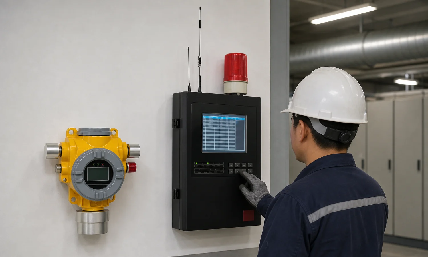
Map the gas hazard before placing detectors
Identify the target gas and the likely release point
A gas name alone is not a specification. Record the expected concentration range and unit for each point, the process equipment involved, and whether the concern is a combustible gas, a toxic gas or oxygen level. The chosen sensor and range must match that task. Do not assume that a long list of possible gases on a product page means one ordered detector measures all of them at once.
Account for airflow, accumulation and access
Walk the area and mark valves, flanges, enclosed spaces and other credible release locations, then mark occupied positions and routes by which gas could reach them. Ventilation, obstructions, gas properties and the location of personnel all affect the value of a proposed point. Leave room for inspection and calibration access. A universal spacing rule or mounting height cannot replace a site-specific point schedule. The UK HSE guidance on flammable gas detectors discusses these placement factors and the distinction between a detector, control unit and alarm.
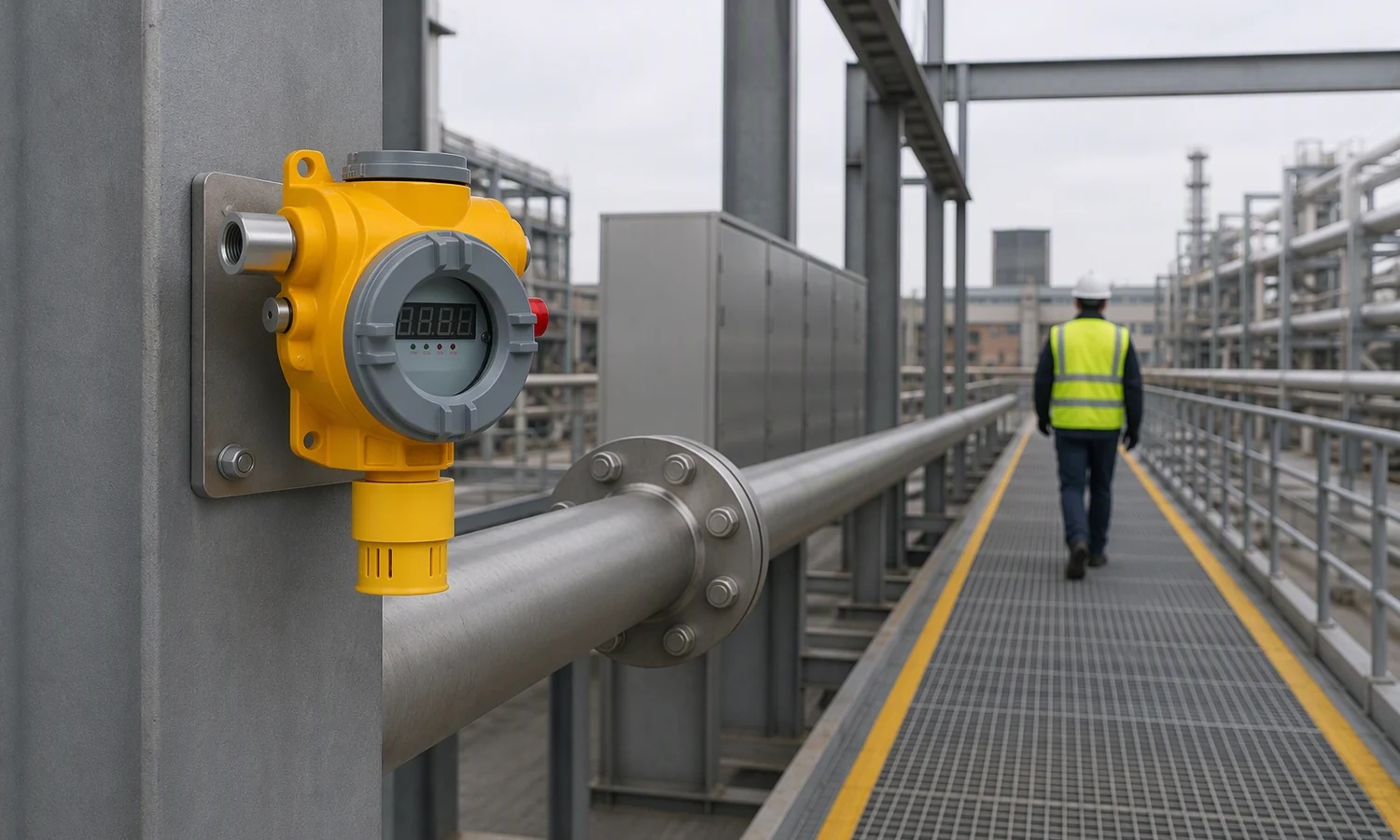
Define the response before specifying the output
Write down who receives an alert, whether the detector needs a local warning, and whether the site intends to signal a control room or another system. If a ventilation or process action is required, identify the responsible interface and its intended behaviour. The ISEA fixed-site selection guide likewise starts with application, danger points and design goals before comparing technology.
Choose the detector by the monitoring task
Diffusion at a defined point
A diffusion detector samples the surrounding air at its installed position. It suits a point selected for the gas and the site conditions. The GTYQ-TCB2 product page lists natural diffusion, local audible and visual indication, and signal options; the gas, range and output are specified for the ordered configuration.
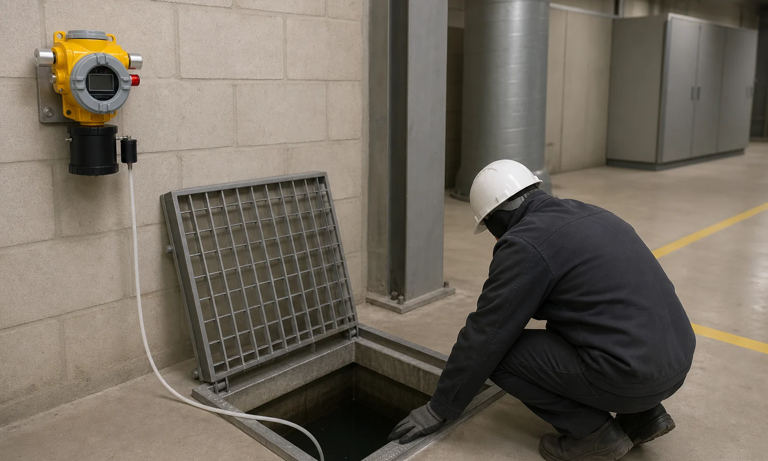
Pump suction where the sample must travel
A pump-suction detector draws a sample to its sensing unit. The TCB2-B page describes an integrated pump and signal options for plant systems. If a sample line is involved, include its route, length, environmental exposure and access for inspection in the project brief. The sample’s travel time is part of the total detection time; a faster sensing element does not cancel a long or obstructed line.
Several gases at one fixed location
If the task calls for several gases at one point, list the exact combination and range for each. The TCB2-F page describes optional one-to-four-gas detection; that is a configuration choice, not a promise that every supplied unit contains four sensors. Confirm the selected sampling version, alarm settings and output protocol for the actual order.
Remote visibility
Where remote readings or alerts matter, define power, network coverage, data recipient and the response when communication fails. The TCB2-W page describes wired and wireless options, with remote features dependent on the selected version. Do not treat every listed communication method as a standard feature on one unit.
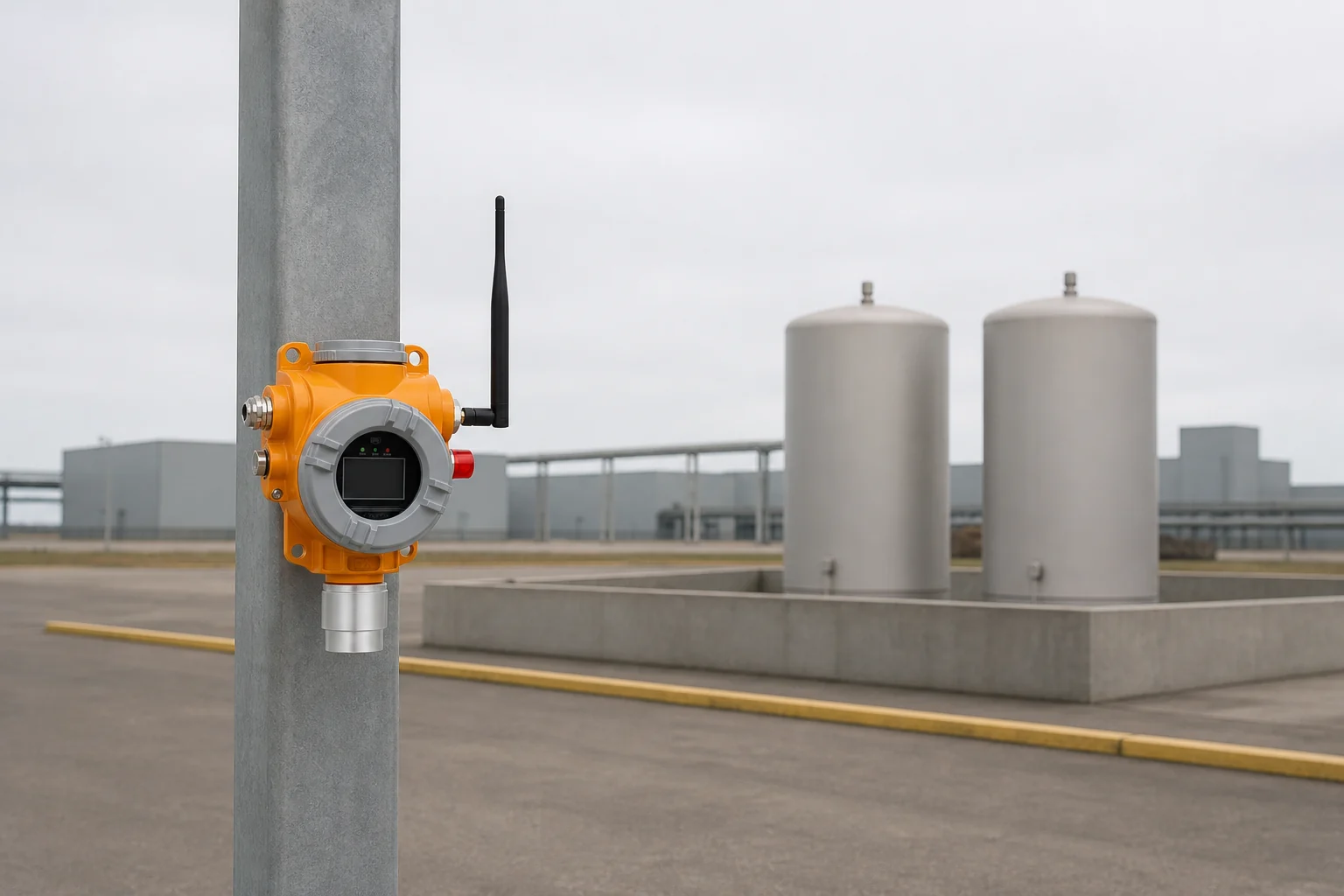
Otywell products for a fixed detection project
These products cover different roles in a project. Select the gas, sampling and signal configuration from the individual product page, then confirm how the chosen devices will work together.
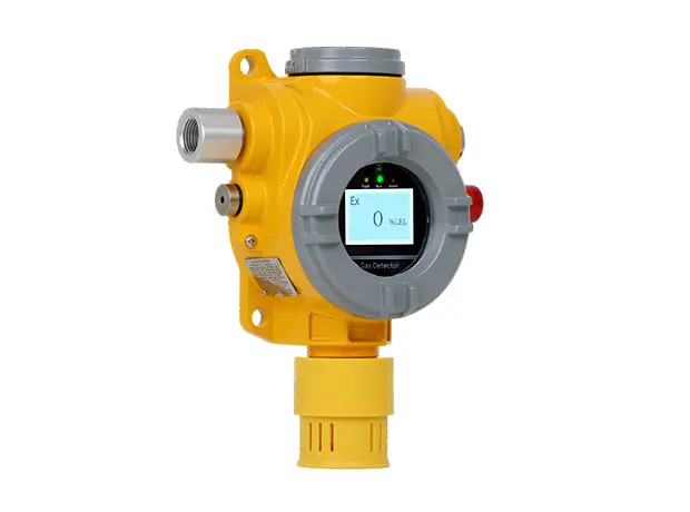 Fixed point
GTYQ-TCB2 Point-Type Gas Detector
Selected-gas monitoring at a fixed point, with local sound and light indication. Output depends on configuration.
View product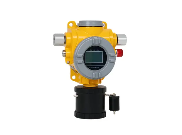 Pump suction
TCB2-B Pump-Suction Point-Type Gas Detector
Draws a sample to a fixed detector with local indication and listed plant-signal options.
View product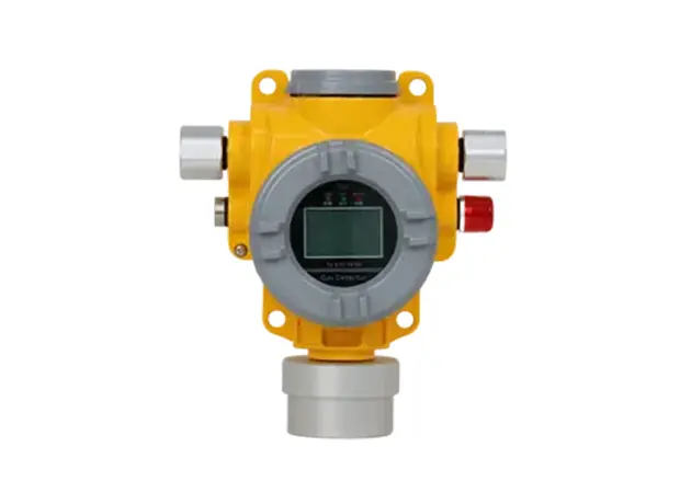 Gas combination
TCB2-F Point Type Four Gas Detector
Offers a selected one-to-four-gas configuration at a fixed point; specify the actual sensor combination.
View product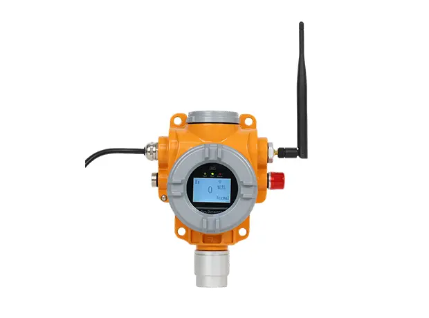 Remote monitoring
TCB2-W Wireless Gas Detection Alarm
Fixed-point monitoring with remote communication options chosen for the installation.
View product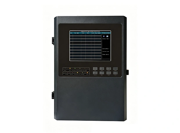 Control
GDB9 Intelligent Gas Alarm Controller
Brings compatible detector signals into an operator view and supports configured alarm handling.
View productMatch signals, controller inputs and alarms
A detector’s output and a controller’s input must be specified as a compatible pair. Otywell product pages list options such as 4–20 mA and RS485 for certain devices, while the GDB9 page lists detector inputs, display and alarm functions. These descriptions do not establish that every detector and controller variant can be combined without checking the actual signal, wiring, power and channel requirements.
| Decision to record | Information needed for each point | Why it matters |
|---|---|---|
| Gas and measurement | Target gas, unit and required range | Determines sensor and configured range |
| Sampling | Diffusion or pump suction; sample-line route if used | Affects point access and total response time |
| Signal path | Selected output, controller input and cable or network plan | Establishes a usable connection |
| Alarm response | Local warning, control-room recipient and any external action | Connects a reading to a defined response |
| Service | Access, test method and fault reporting | Allows the installed point to be checked over time |
Plan for commissioning and continued access
Before installation, consider how each point will be identified, tested and reached again. For a pumped installation, inspect the whole sampling path as well as the instrument. For any fixed detector, retain the exact product and sensor configuration used for the point, together with its applicable operating and calibration instructions. Test the alarm path as a chain: detector indication, transmitted signal, controller display, fault indication and the agreed site response. The HSE guidance specifically notes that sampling lines can add delay and can be affected by blockage or contamination.
Where fixed monitoring fits
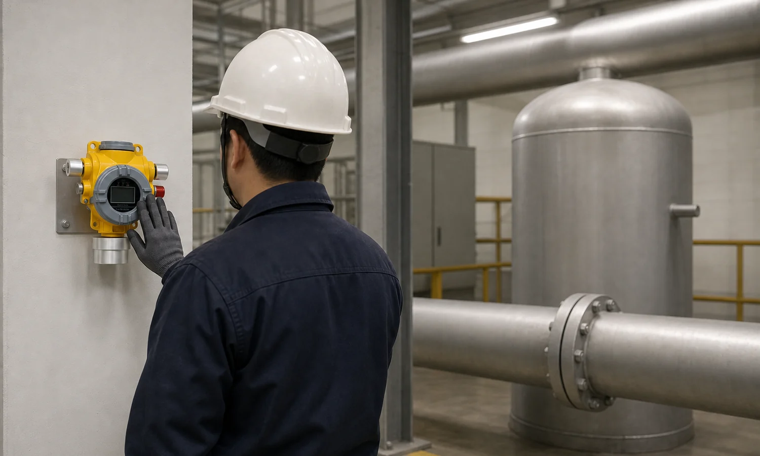
The same selection sequence applies across different industrial settings, but the point schedule changes. A chemical room may need attention to storage and handling positions; a steel plant may have several process gases and distributed points; a ship engine room adds its own layout and signal-routing constraints. Begin with the actual release sources and intended alarm recipients for that site, then choose the equipment and configuration that fit them. A general industry label alone does not settle detector placement.
Prepare a useful system enquiry
Send the application and site area, target gases, number of proposed monitoring points, range and unit at each point, diffusion or pump-suction preference, required signal or controller interface, and installation and power conditions. If an alarm must reach another system, describe that action as well. This gives the product and engineering team a concrete starting point for selecting configurations.
Frequently asked questions
What is included in a fixed gas detection system?
The project may include field detectors, a receiving or control device, power and signal connections, and local or remote alarms. Some functions may be combined in one product; the supplied scope depends on the selected configuration.
How do I choose the gas and measurement range for each point?
Start with the gas that could reach that point, the purpose of monitoring and the unit in which the result must be reported. Specify the required range for that gas rather than copying a general range from another configuration.
When should I consider pump suction rather than diffusion?
Consider it when the sensing unit needs to draw a sample from a defined location. Record the sampling route, possible line delay and how the line will be inspected; those factors affect the whole installation.
Can one fixed detector monitor multiple gases?
A suitable multi-gas configuration can do so. For example, the TCB2-F page lists optional one-to-four-gas detection. The ordered sensor combination and ranges determine what the specific unit monitors.
What must be checked before connecting a detector to a controller?
Check the detector’s selected output against the controller’s input, then confirm power, wiring, channel count, alarm logic and any external interface for the exact versions being ordered.
What should be checked for a wireless fixed detector?
Confirm the selected communication version, power arrangement, coverage at the intended point, recipient of remote data and how a communication fault will be noticed.