Ship engine room gas and flame monitoring solution
A coordinated engine room safety system for continuous gas monitoring, optical flame detection, central alarm management, portable sampling, and leak investigation.
Fuel systems, hot surfaces, rotating machinery, electrical equipment, and forced ventilation all share the same enclosed machinery space. A release from a seal, flange, hose, or valve may be carried away from its source by the airflow. If liquid fuel reaches a hot surface, the event can move from leakage to fire before the source is visible.
This solution follows that sequence. Fixed detectors watch selected gas risk points, infrared flame detectors cover areas where a hydrocarbon fire may develop, and the GDB9 brings their signals into the engine control room. The OT135S supports atmosphere checks during inspection and maintenance, while the OT131 helps technicians narrow down an accessible leak source after the area has been assessed.
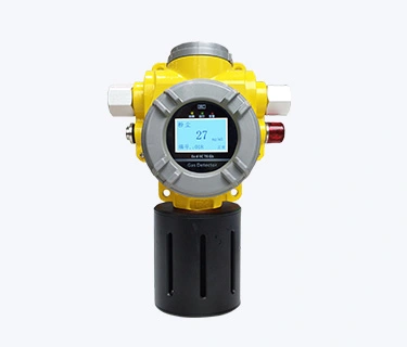
Fixed gas monitoring near fuel equipment in a ship engine room.
A system built around five defined functions
| Product | Role in the solution | Typical use point |
| TCB2-F point-type four-gas detector | Continuous measurement at selected gas risk points | Fuel treatment equipment, valve groups, pumps, and other locations identified in the vessel risk assessment |
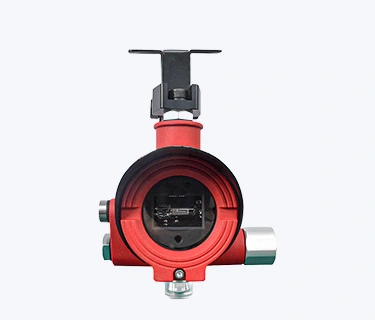
| S600-ExR3 infrared flame detector | Optical detection of liquid and gaseous hydrocarbon flames | Areas with a clear view of fuel handling equipment and machinery exposed to fire risk |
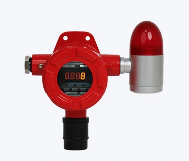
| GDB9 gas alarm controller | Central display, alarm processing, event records, and configurable outputs | Engine control room or another approved indoor control location |
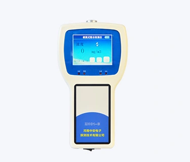
| OT135S portable multi-gas detector | Pump-sampled pre-checks and local atmosphere testing | Checks before closer approach, followed by rounds, inspection, and maintenance work |
| OT131 handheld gas leak detector | Close-range leak source investigation | Accessible fuel lines, valves, flanges, flexible connections, and fittings |
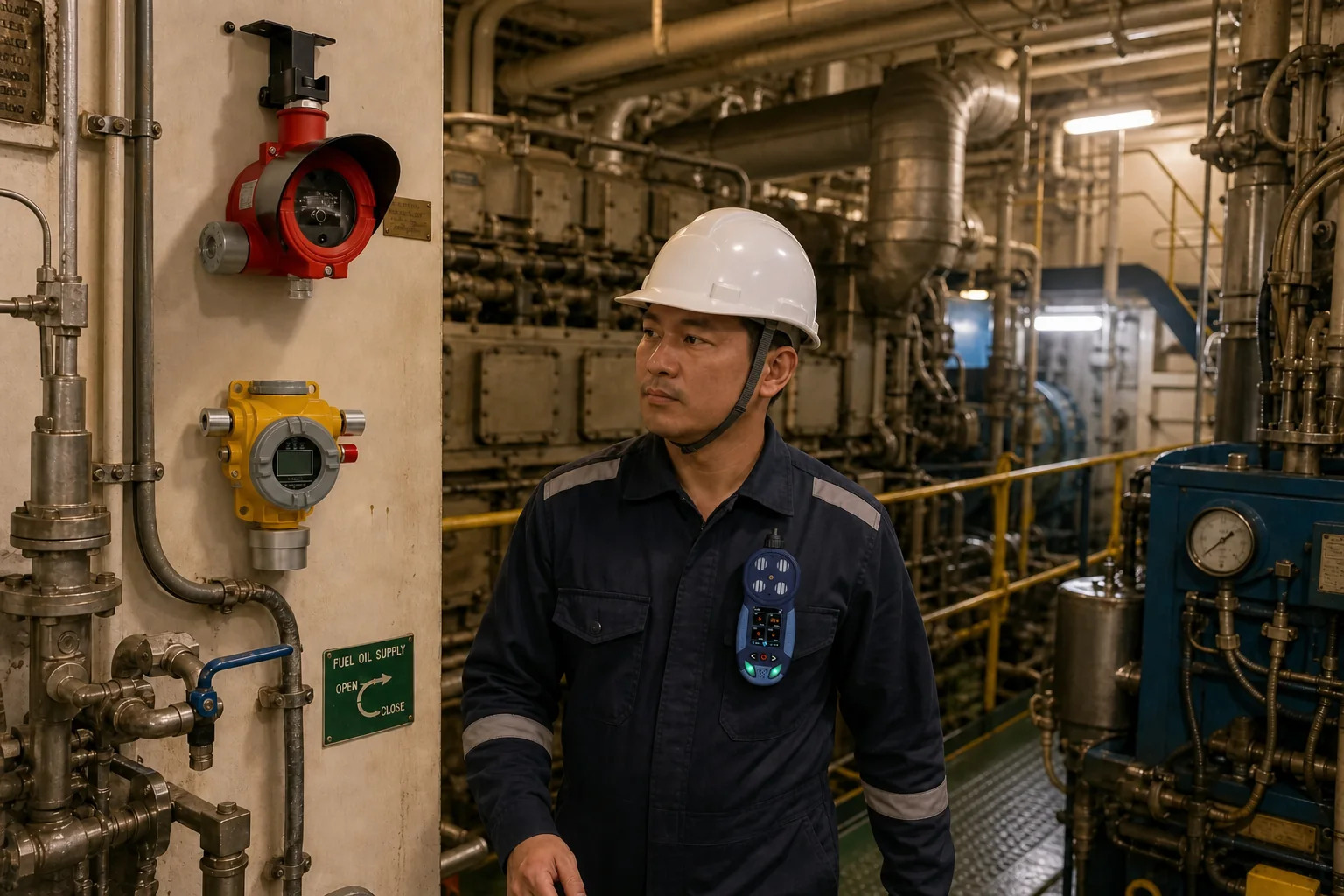
OT135S portable multi-gas detector selected for marine inspection and sampling work.
Materials selected for the marine environment
Equipment installed in the machinery space needs a housing suited to persistent humidity, salt-laden air, oil mist, and routine cleaning. In this configuration, both the fixed gas detection probe and the S600-ExR3 flame detector have stainless-steel housings.
The GDB9 is intended for an approved indoor control location. Its enclosure is ABS, and the printed circuit board is finished with conformal coating to protect the electronics from moisture, salt mist, and airborne contamination. Cabinet position, ventilation, and cable entry remain part of the vessel’s electrical design.
For portable work, the OT135S combines a high-strength engineering-plastic enclosure with anti-slip rubber protection. The model supplied for this solution carries marine certification and is configured for shipboard atmosphere checks and sampling duties.
The configuration is specific to an engine room. Cargo holds, ballast tanks, pump rooms, and offshore process modules involve different release patterns, access conditions, and approval requirements, so they should be engineered as separate applications.
Detection coverage across the engine room
Combustible gas around fuel equipment
The TCB2-F provides continuous measurement at the points where a release is most likely to appear or accumulate. It can be configured with up to four gas channels, including combustible gas, oxygen, hydrogen sulfide, and carbon monoxide. The selected channels depend on the fuel, machinery arrangement, ventilation, and findings of the vessel risk assessment. Signals are available through 4 to 20 mA or RS485 for connection to a compatible controller.
The fixed probe supplied for this marine application has a stainless-steel housing. Sensor configuration, cable entry, mounting hardware, and the exact material specification are confirmed with the final order.
Placement begins with the likely source and the way air moves around it. Gas density is relevant, but it cannot describe the effect of supply fans, extraction points, machinery heat, or local turbulence. A detector mounted at the expected high or low point may still miss a release if the ventilation carries the gas in another direction.
Hydrocarbon flame risk
A gas detector measures the atmosphere at one location. A flame detector looks across an area for the radiation produced by fire. Using both closes the gap between an unignited release and a fire that has already started.
The S600-ExR3 uses three infrared channels. The primary channel responds to the carbon dioxide emission band associated with hydrocarbon combustion, while the remaining channels help the detector distinguish flame signatures from background infrared sources. It is intended for liquid and gas hydrocarbon fires, including open flames with smoke and deflagration hazards.
Its effectiveness depends on sightline. Pipework, structural members, cabinets, and later changes to machinery can obscure the target area, so coverage must be reviewed against the actual layout rather than calculated from detector quantity alone.
The S600-ExR3 in this marine configuration has a stainless-steel housing. Brackets, fasteners, cable glands, and junction arrangements should be specified for the same service environment.
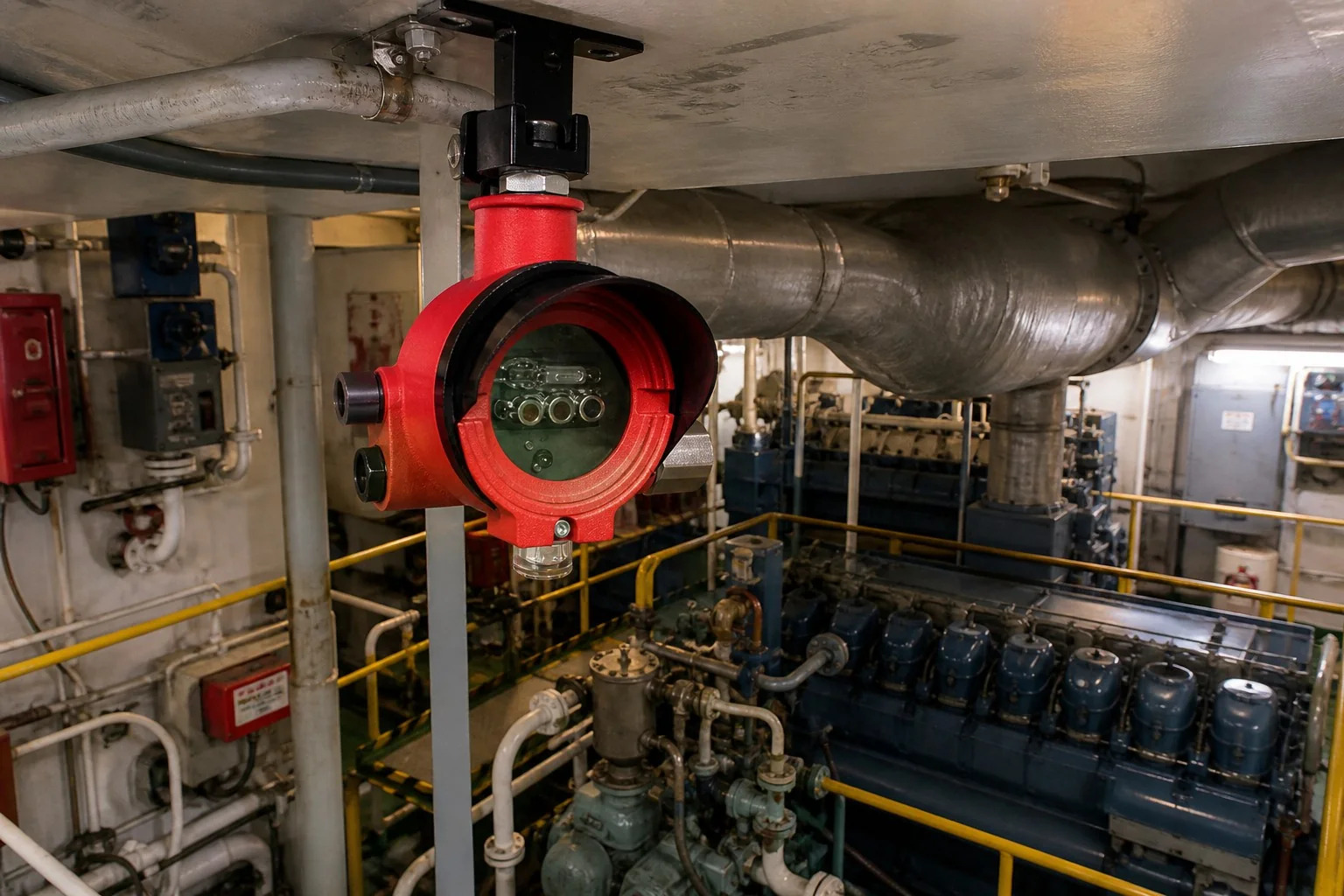
S600-ExR3 infrared flame detector with a clear view of engine room machinery.
Portable atmosphere checks during rounds and maintenance
A fixed network cannot follow every route taken during inspection or maintenance. The OT135S portable gas detector extends coverage to the work location and can measure one to four gases at the same time.
Its built-in pump is used when the atmosphere needs to be sampled before the operator moves closer. Once at the work location, natural diffusion provides a local reading around the instrument. Audible, visual, and vibration alarms make a change in conditions difficult to overlook in a noisy machinery space.
A typical four-gas selection may include combustible gas, oxygen, carbon monoxide, and hydrogen sulfide. The actual gas list, measurement ranges, alarm settings, sampling line, filters, and certificate are confirmed for the ordered marine configuration.
Small leaks at accessible connections
A fixed alarm identifies the affected monitoring area, but it may not reveal which seal, flange, hose, or fitting is leaking. Once access has been assessed and authorized, the OT131 gives the maintenance team a close-range instrument for tracing an accessible source.
The OT131 is ordered for the gas under investigation. Its role is leak localization. Area monitoring remains with the TCB2-F network, while the OT135S is used for multi-gas sampling and atmosphere checks.
From field detection to an informed response
1. Fixed detectors watch selected risk points
The TCB2-F point-type four-gas detector measures the selected atmosphere near fuel equipment and other designated risk points. When the reading changes, the detector sends its signal to the control location.
The detector operates on 24 VDC and supports 4 to 20 mA or RS485 output, depending on the wiring design. Engine room alarms can therefore be observed centrally, without depending on a crew member being close enough to notice the field display.
2. The controller processes alarms and outputs
The GDB9 accepts multiple 4 to 20 mA or RS485 channels and presents them on a color touch display. Audible and visual alarms draw attention to the affected channel, while six passive switch outputs are available for functions defined in the vessel’s approved cause and effect design.
Those outputs may pass signals to ventilation, shutdown, valve, or other ship systems, but the required action cannot be determined by the relay alone. The shipyard, owner, and relevant approval authority must agree on the logic, then verify it during commissioning.
Alarm and fault records, configurable setpoints, manual reset and mute, fault self-checking, and automatic main and backup power switching support day-to-day operation. Optional 4G upload can be specified where the vessel’s network and data policy allow it.
The controller has an ABS enclosure and a conformal-coated printed circuit board. Its protection is completed by the installation itself, including cabinet location, ventilation, cable entry, and environmental control.
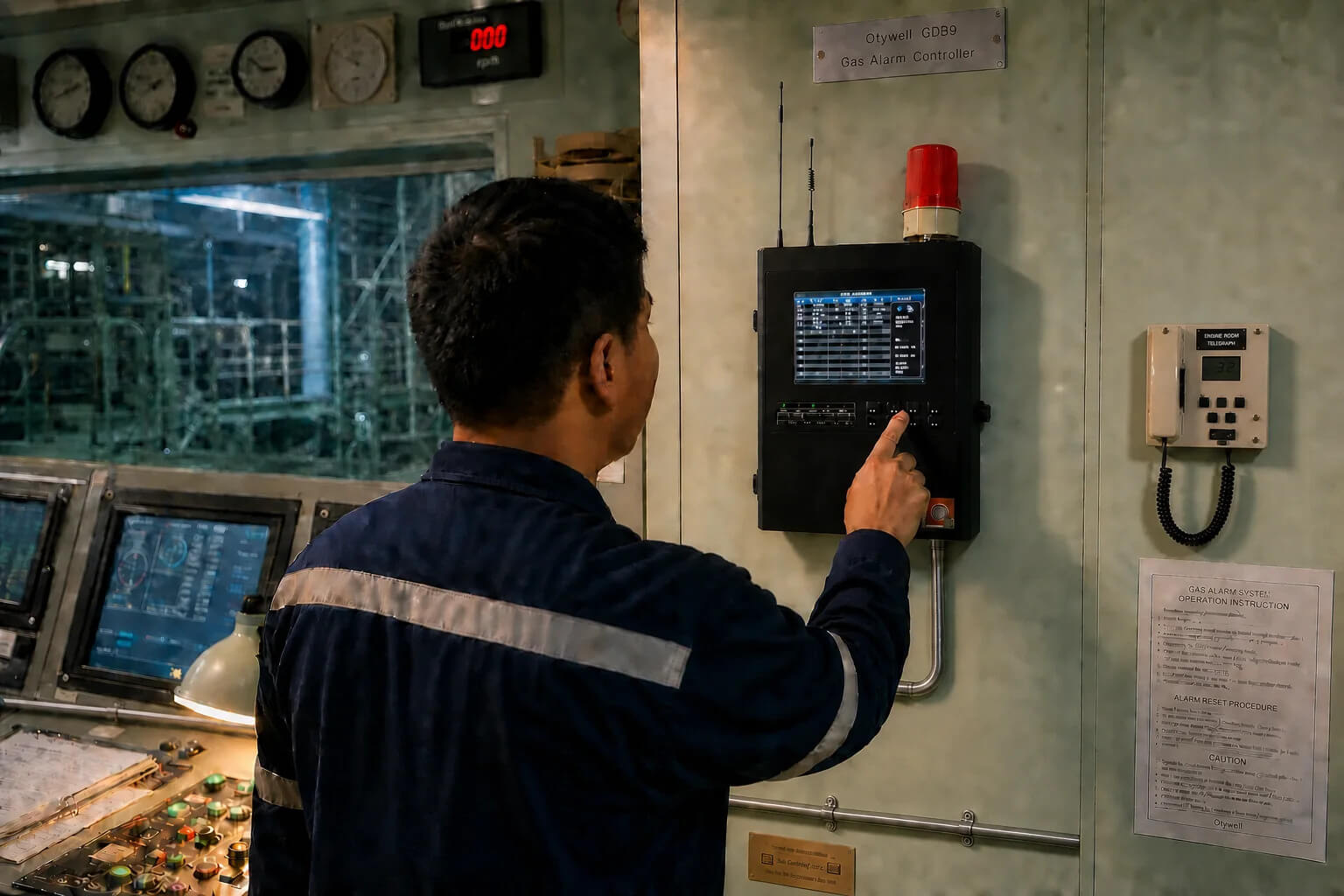
GDB9 controller displaying gas alarm channels in the engine control room.
3. Flame detectors cover the selected field of view
The S600-ExR3 flame detector is mounted on a wall or ceiling with a clear view of the protected area. The published viewing angle is up to 110 degrees, with a response time of 6 seconds under the stated test conditions.
Relay and RS485 outputs allow the detector to report into the alarm architecture. The IP66 enclosure and Ex d IIC T6 Gb marking form part of the technical review. Final acceptance still depends on the exact product approval, installation design, flag requirements, and classification rules for the vessel.
4. Crew use the OT135S for pump-sampled and local checks
Before a round or maintenance task, the crew confirms the OT135S sensor configuration, alarm settings, battery condition, bump test and calibration status. The sampling path, filter, and pump also need attention when remote sampling is planned.
With the appropriate line connected, the built-in pump draws gas from the selected point. The operator must allow for line length and sample travel time before accepting the reading. Natural diffusion is available when the instrument is being used for a local atmosphere check.
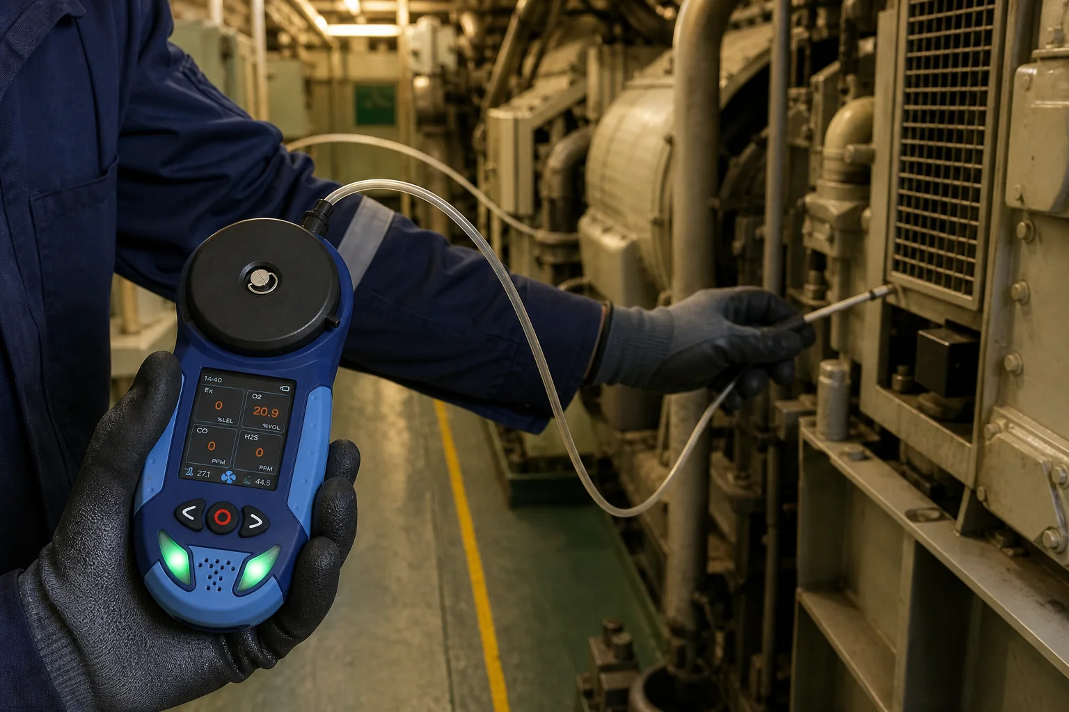
OT135S portable detector configured for pump-sampled and diffusion gas checks.
5. Maintenance teams trace accessible leak points
After the alarm has been assessed and access is under control, the OT131 can be moved around accessible joints and connections to narrow down the source. Its target gas and measurement range must match the substance under investigation.
The reading informs the inspection; it does not authorize intervention. Tightening a connection, opening equipment, or continuing operation remains subject to the vessel’s isolation, permit, and hot-work controls.
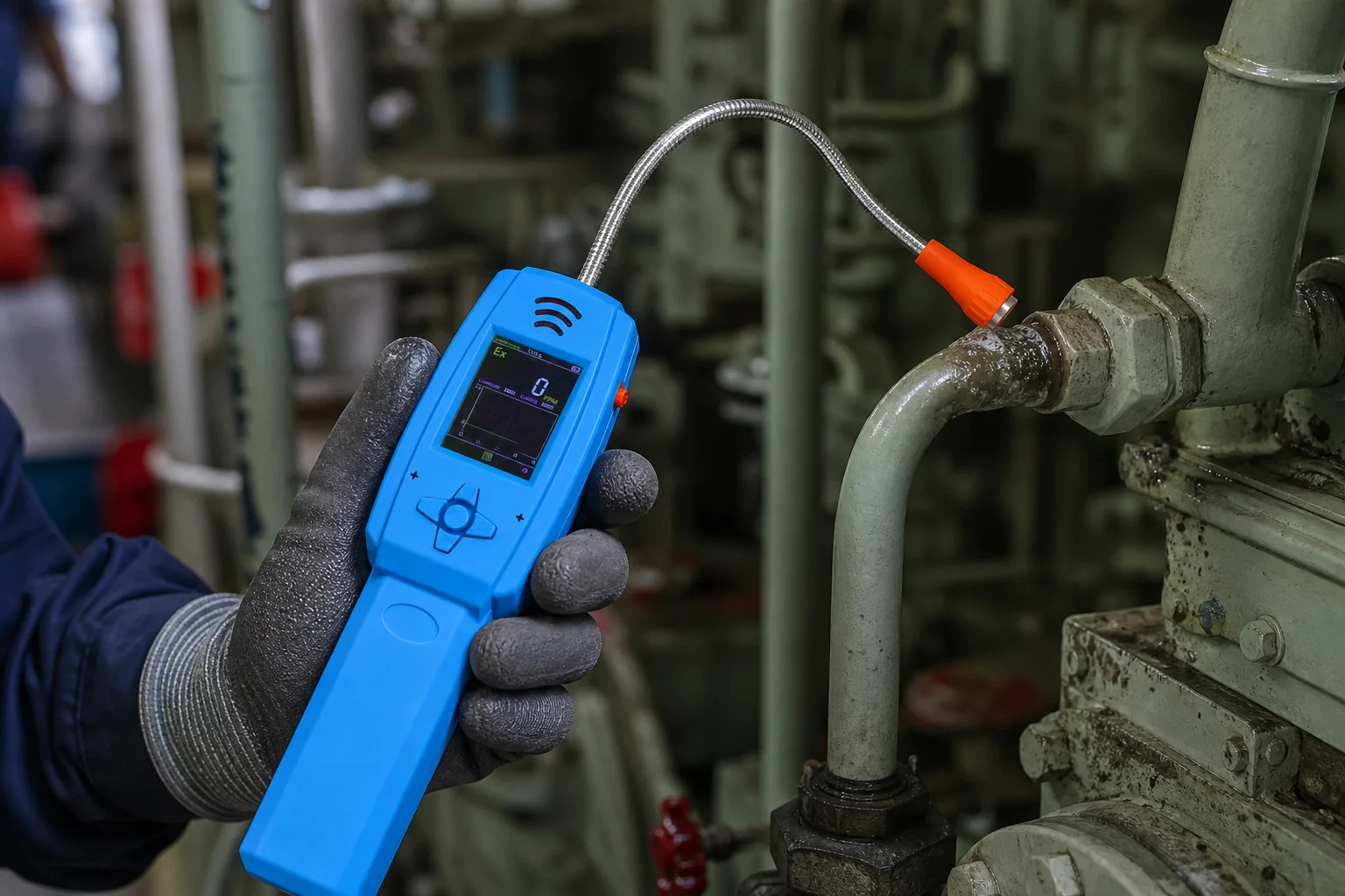
OT131 handheld detector checking an accessible fuel pipe connection.
Recommended monitoring layout
| Engine room area | Main concern | Selected equipment | Design point |
| Fuel pumps and filters | Combustible release from seals or connections | TCB2-F | Locate after reviewing release sources and local airflow |
| Fuel valve and manifold area | Leakage at valves, flanges, or fittings | TCB2-F and OT131 | Combine fixed warning with close inspection during authorized maintenance |
| Machinery and fuel handling zone | Liquid or gas hydrocarbon flame | S600-ExR3 | Keep an unobstructed optical field of view |
| Engine control room | Alarm display and output management | GDB9 | Install indoors in an approved location |
| Crew rounds and maintenance route | Pre-checks and changing local atmosphere during inspection | OT135S | Use pump sampling before closer approach and diffusion for local checks |
Layout note
This table defines the monitoring concept, not the final detector coordinates. Quantity and position are resolved from the engine room dimensions, supply and exhaust airflow, fuel properties, machinery arrangement, obstructions, hazardous area classification, and required alarm actions.
Alarm and response logic
Detection becomes useful when the alarm identifies the affected area and passes the right information to the people responsible for the response. The system configuration therefore follows the vessel’s approved alarm philosophy and cause and effect chart.
A typical operating sequence is:
1. A fixed gas or flame detector registers an alarm condition.
2. The GDB9 identifies the channel and activates the audible and visual alarm.
3. Configured relay outputs pass the defined signal to connected systems.
4. The responsible crew follows the vessel’s response procedure and controls access.
5. The OT135S supports pump-sampled pre-checks, targeted sampling, and local atmosphere testing when inspection is authorized.
6. Alarm, fault, test, and maintenance records are retained under the vessel’s recordkeeping procedure.
Project-specific alarm logic
Alarm thresholds and automatic actions are set for the vessel. Fuel type, machinery, ventilation, flag requirements, class rules, and the existing automation system all influence the final cause and effect design.
Installation and commissioning
Hazard and vessel review
Design starts with the vessel type, engine room drawings, fuel data, ventilation arrangement, hazardous area classification, existing alarm system, available power, and required approvals. The review also defines the monitoring points and the intended response for every alarm channel.
Detector and controller selection
The resulting specification covers target gases, measurement ranges, sensor principles, fixed detector outputs, controller channel capacity, flame coverage, and the portable detector configuration. Certificates are checked against the destination vessel and market before the order is released.
Mounting and wiring
Fixed detectors are installed at the approved points and connected to the GDB9 or a compatible vessel control system. Cable type, routing, segregation, glands, grounding, and protection follow the electrical design. Flame detector sightlines are checked again after mounting.
Functional testing
Commissioning covers every detector channel, controller indication, audible and visual alarm, fault signal, relay output, and connected action. Channel names are checked against the physical locations so an alarm directs the crew to the correct part of the engine room.
Crew handover
Handover documentation records the final configuration, alarm setpoints, channel list, test results, calibration instructions, spare requirements, and maintenance schedule. Crew training covers fixed alarms, OT135S checks, the limits of leak investigation, and the required response to a fault or overdue calibration.
Maintenance plan
A detector that cannot be tested cannot provide dependable protection. Salt, oil mist, dust, vibration, heat, cleaning residue, paint, and physical obstruction can all change the condition of field equipment over time.
The maintenance plan covers:
● Visual inspection of detector condition and mounting
● Bump testing and calibration at the required interval
● Flame detector window inspection and cleaning
● Controller alarm, fault, and relay tests
● OT135S charging, sampling inlet, filter, line, and pump checks
● Sensor and battery replacement planning
● Review of alarm and fault records
● Reassessment after machinery, ventilation, or fuel changes
Frequently asked questions
Which gases should be monitored in a ship engine room?
The gas list comes from the fuel, machinery, ventilation, and vessel risk assessment. Combustible gas is commonly monitored where a flammable release may reach a fixed point. A portable configuration may also include oxygen, carbon monoxide, and hydrogen sulfide. The same four-gas selection should not be applied to every engine room without review.
Why does this solution include both gas and flame detection?
A gas detector measures a target gas at its sensing point, which can provide warning before ignition. A flame detector responds to the radiation produced by a fire within its field of view. They address different stages of the same hazard.
Where should fixed gas detectors be installed?
Start with credible leak sources, then review local airflow, fuel properties, room geometry, access, and hazardous area classification. Fuel pumps, filters, valve groups, and treatment equipment are common review points, but the final coordinates must follow the vessel layout.
Can the GDB9 control ventilation or shutdown equipment?
Yes, where the approved cause and effect design calls for it. The GDB9 has configurable passive switch outputs that can pass alarm or control signals. The connected action, wiring, fail-safe behavior, testing, and approval requirements are defined at system level.
What is the role of the OT135S portable detector?
The OT135S supports checks beyond the reach of the fixed detector points. It can use pump suction for pre-checks and targeted sampling, then operate by natural diffusion for local atmosphere testing. One to four gas channels and audible, visual, and vibration alarms are available. Sensors, ranges, accessories, and the marine-certified configuration are selected to match the vessel’s procedure.
When is the OT131 used?
Use the OT131 when an assessed and controlled inspection needs to narrow a suspected leak down to an accessible valve, flange, hose, fitting, or pipe connection. It is configured for the target gas and range. The OT135S remains the instrument for multi-gas pre-checks and local atmosphere testing.
How should the flame detector be selected and positioned?
Selection follows the expected fuel and fire type. Positioning then accounts for sightline, machinery, pipework, maintenance access, and possible infrared interference. The final quantity and viewing angles are confirmed through a coverage review.
What information does Otywell need for a proposal?
The first review needs the vessel type, engine room drawings, fuel information, target gases, room dimensions, ventilation arrangement, hazardous area classification, required alarm actions, available power, controller requirements, and destination approvals. Current photographs of the machinery and proposed detector locations help resolve sightlines and access.
Request an engine room monitoring proposal
Share the engine room layout, fuel information, target gases, ventilation arrangement, and alarm requirements. Otywell will develop a coordinated equipment schedule covering fixed gas detection, flame coverage, central alarm control, OT135S portable sampling, and OT131 leak investigation.
Discuss your marine gas detection project