
A commissioning sheet is useful only if it tells you what was tested, what the system was supposed to do, and what it actually did. Work from the approved point schedule through the detector, controller and final alarm action. Record a failure at the step where the chain breaks, then repeat the affected test after the correction.
For each fixed gas detector, confirm the installed point and configuration, prove its channel identity, apply the specified test gas at the normal sampling entry, and observe the alarm and fault paths through to the actions defined for that installation. Close every failed item, remove temporary bypasses, and hand over the final settings and test records.
- Approve the test basis
- Walk each point
- Challenge the detector
- Prove final actions
- Restore and hand over
1. What must be ready before the first test?
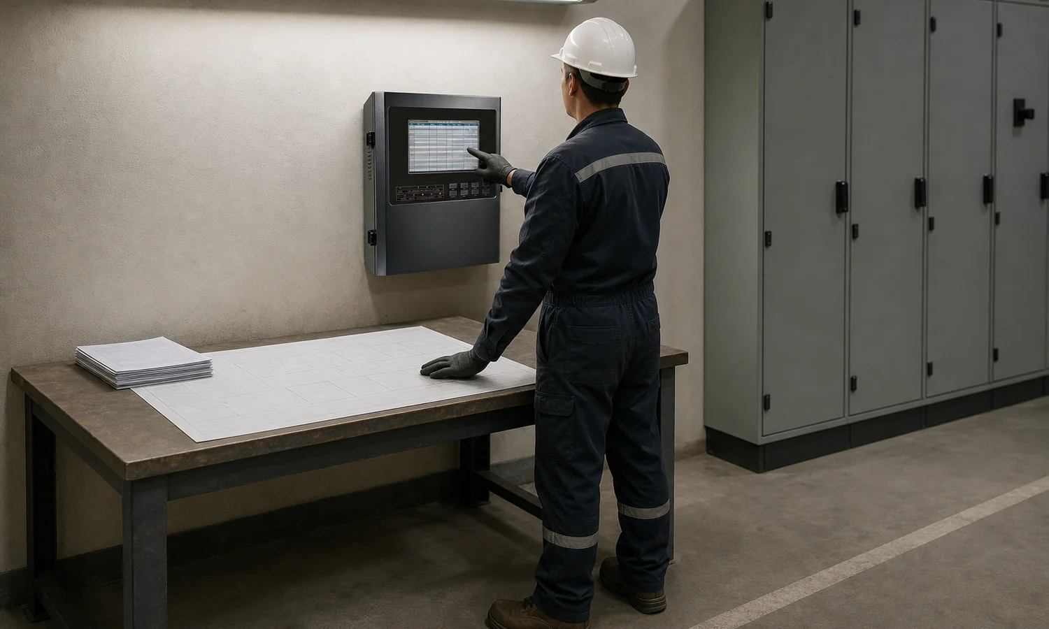
Do not begin with a cylinder in your hand and a list of detector tags from memory. Put the current point schedule, wiring drawings, ordered equipment configurations and cause-and-effect matrix on the test desk. One row should identify the physical tag, location, target gas, range and unit, output type, receiving channel, alarm settings and required final actions. If the controller configuration and the drawings disagree, record the difference before anyone calls the point a pass.
Agree who applies the test, who watches the controller, who observes any connected equipment, and who owns a temporary isolation. Keep a record of the isolation before the trigger is applied and of its removal afterward. The test gas, regulator, cup or sampling accessory, cylinder ID and expiry also belong on the sheet. A result with no traceable test setup cannot be reproduced later.
Table 1. Pre-test readiness checklist
| Item | Action before testing | Required evidence or decision |
|---|---|---|
| Point schedule | Match every field tag to location, gas, range, unit and controller channel. | Approved revision; list any unresolved mismatch. |
| Cause-and-effect matrix | Identify the expected local, controller and external action for each trigger. | Matrix revision and witness for each final action. |
| Test equipment | Check gas identity and concentration, cylinder ID/expiry and model-specific accessories. | Record the setup assigned to each point. |
| Temporary isolation | List affected outputs, approval, observing method and restoration owner. | Isolation register; do not mark an unwitnessed final action as passed. |
Hold point: If a point has no approved expected result, label it “awaiting test basis” rather than filling in Pass. That single distinction keeps an incomplete design decision out of the acceptance record.
2. Walk down every detector point before energizing
Walk the schedule in tag order and start at the actual mounting position. Compare the field label, model and gas configuration with the drawing. Look at the sensor or sample entry, enclosure, cable entry, supports and access needed for future testing. Record what you see and the drawing revision used; “installed” is not a useful observation when a later technician has to find a mislabeled device.
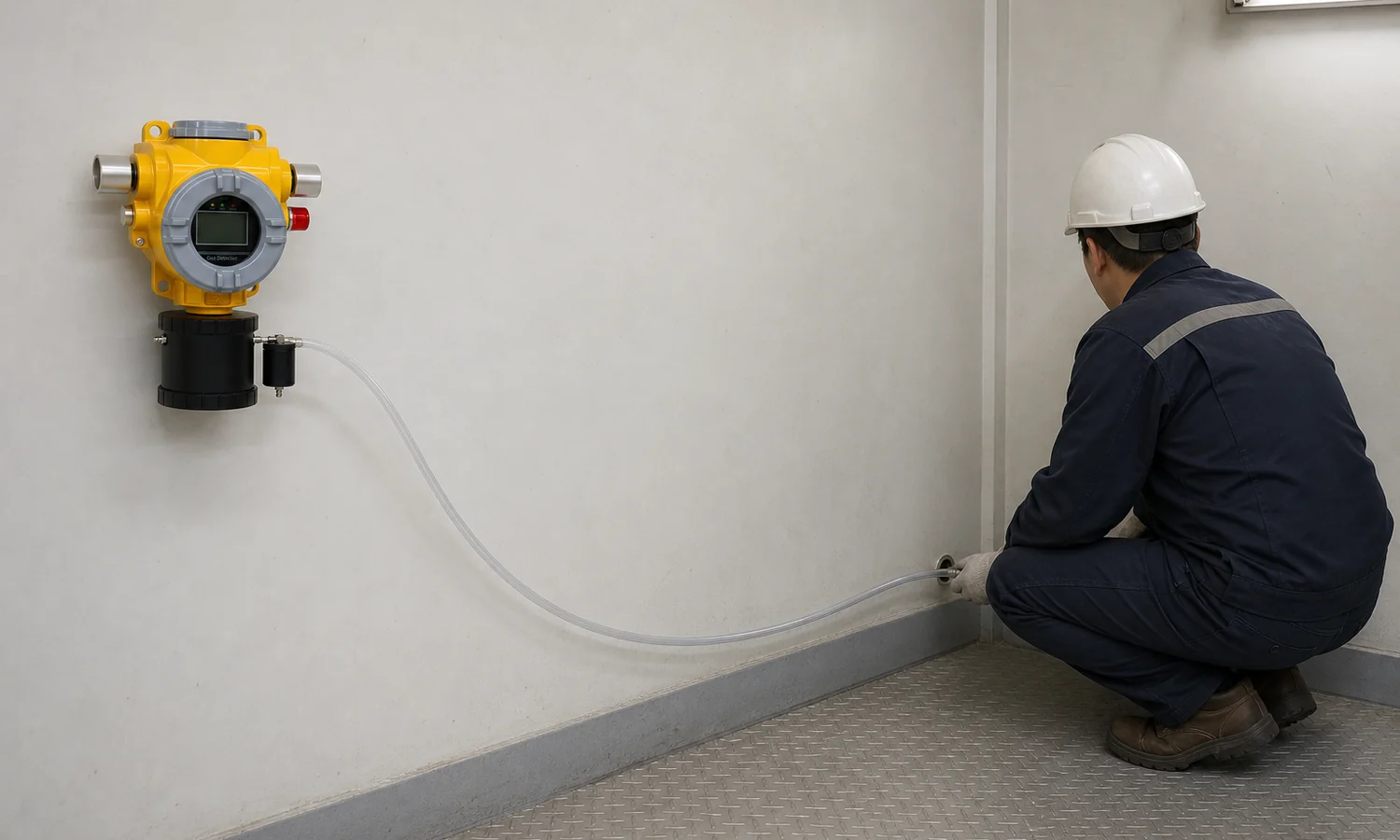
For a pump-suction point, trace the route from the remote inlet to the detector, including accessible connections and any installed filter or water trap. A test made only at the instrument inlet proves less than a test of the installed sampling route. The UK HSE safety alert on unsuitable sampling tubes describes how the tube itself can prevent the target vapour from reaching an otherwise functioning detector.
Table 2. Field point walkdown
| Check | Do this at each tag | Record |
|---|---|---|
| Identity | Read field tag, model, gas label and range against the point schedule. | Observed values, drawing revision and Pass/Fail. |
| Physical installation | Inspect mounting, enclosure, inlet and cable entry against the supplied instructions. | Photo or defect ID for anything different. |
| Test access | Locate the normal gas entry and the means of reaching it. | Application point to use in Table 4. |
| Pumped route, where fitted | Follow the remote inlet, tubing and installed accessories to the instrument. | Route sketch, inlet tag and any restriction or damage. |

3. Prove the channel and signal mapping
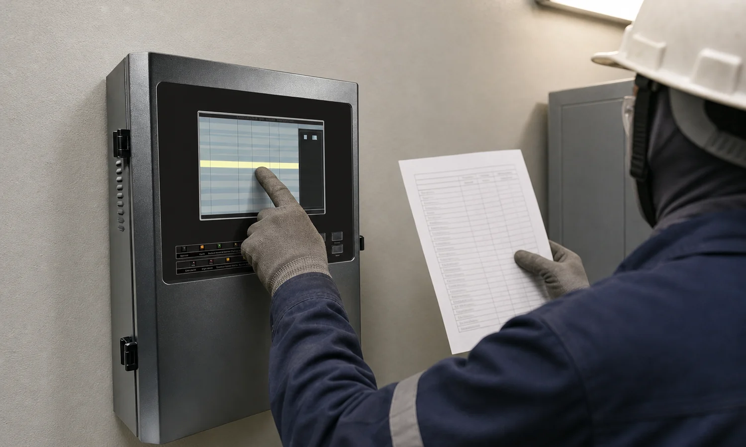
After the model’s required start-up and stabilization steps, compare the field device with the controller one point at a time. The tag, gas name, unit, range and normal or fault state must refer to the same physical detector. An apparently plausible reading on the wrong channel is still a failed test. Where a control-room display receives the data separately, verify its point name and value too.
For an analogue output, check the configured scaling and engineering unit at the receiver. For a digital link, check the device address and channel assignment. Then use the approved test method to verify that a lost or failed input appears as a fault rather than a normal-looking value. The UK HSE gas-detection guidance treats undetected detector failure and failed alarm operation as distinct hazards; the commissioning record should do the same.
Table 3. Input and display mapping matrix
| Field tag and output | Expected receiver identity | Observe and record | If different |
|---|---|---|---|
| Detector tag, gas, range and unit | Approved controller channel and label | Field display; panel label, value and unit; evidence ID | Check tag and point schedule first. |
| Analogue output, if fitted | Approved input scaling | Panel engineering value against field value | Check range, unit and input configuration. |
| Digital output, if fitted | Approved address and channel | Address, status and control-room point name | Check address, wiring and point mapping. |
| Fault or lost link | Documented fault indication | Field, panel and remote fault state | Trace the failed section; retest after correction. |
4. Apply test gas and document the actual response
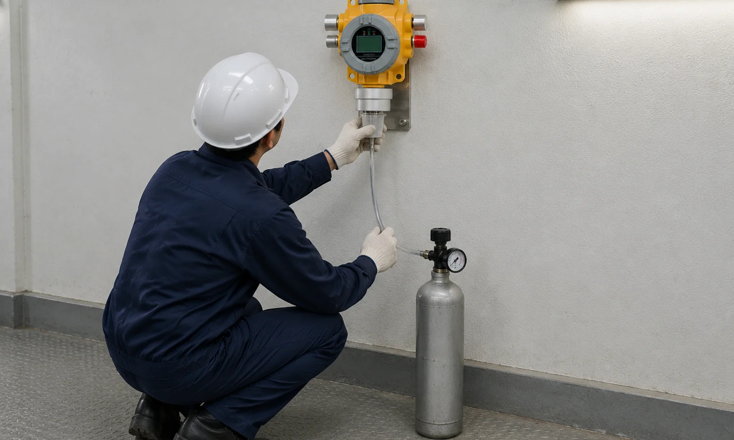
Use the test gas, concentration, accessories and procedure specified for the installed sensor and its actual configuration. Record the cylinder ID and expiry, the application point, the starting reading and the observed response. Keep a calibration or adjustment record separate from the installed-point functional test. A calibrated sensor can still be connected to the wrong channel or a blocked sampling line.
On a diffusion point, apply gas at the inlet specified for that model. On a pumped point, challenge the normal remote sampling entry when proving the complete installed route. Watch the detector, controller and any configured alarm while the gas is applied; then record recovery after the gas is removed. If the approved acceptance basis includes response time, measure the actual interval. Do not borrow a time or flow figure from another model.
Table 4. One record per gas challenge
| Record field | What the tester enters | What it proves |
|---|---|---|
| Point and setup | Tag; gas/range/unit; cylinder gas, concentration, ID and expiry; accessory | The correct point and test material were used. |
| Application | Diffusion inlet or remote pumped inlet; date, operator and start time | The normal detection path was challenged. |
| Response | Initial and observed readings; alarm state and time; panel event ID | Actual behaviour can be compared with the approved criterion. |
| Recovery | Reading and alarm state after gas removal; reset result | The point returns to the required normal state. |
| Disposition | Approved criterion, Pass/Fail, defect ID and retest ID | A failed point stays open until the affected path passes. |
When the readings disagree: If a near-instrument check responds but the remote inlet check does not, inspect the sample route and repeat the inlet test. If the field reading changes but the controller does not, return to the channel mapping in Table 3.
Otywell equipment in the test path
A fixed-system test sheet follows the devices actually supplied. These four product types illustrate the controller, diffusion, pumped and configurable multi-gas points that may appear on a project schedule. The ordered gas, range, signal and accessories determine the test method for each tag.
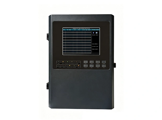 Controller
GDB9 Intelligent Gas Alarm Controller
Receives configured detector inputs and provides display, alarm and relay functions for a fixed system.
View GDB9 controller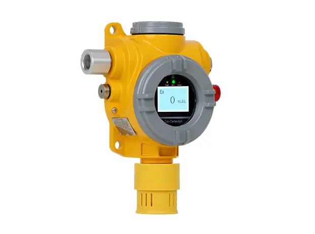 Diffusion point
GTYQ-TCB2 Point-Type Gas Detector
Natural-diffusion fixed detector with local sound and light indication; signal options depend on configuration.
View GTYQ-TCB2 detector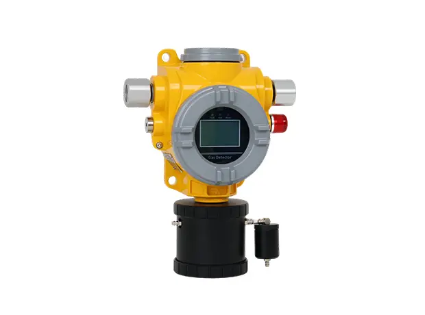 Pumped point
TCB2-B Pump-Suction Point-Type Gas Detector
Integrated-pump fixed detector with local indication and listed plant-signal options.
View TCB2-B detector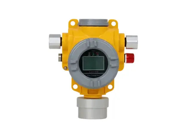 Gas combination
TCB2-F Point-Type Four-Gas Detector
Available with a selected one-to-four-gas configuration at a fixed point.
View TCB2-F detector5. Run cause-and-effect tests to the final action
A detector response in Table 4 is the start of an integrated test, not its end. For each trigger in the approved cause-and-effect matrix, watch every required step: field indication, controller tag and alarm level, event record, output state, receiving system and the final action. Low and high alarms, detector faults, communication faults and restoration of power are separate rows when they exist in the design. Do not mark a ventilation fan or valve as passed because a relay clicked in the panel.
Arrange witnesses at the final equipment before the trigger. If an action has to be isolated during a test, record the isolation and the point at which the chain was observed. A simulated input and a witnessed final action are different results. The University of Calgary fixed gas detection page separates system requirements from a sequence of operations for connected building systems; this is the same distinction the test matrix must preserve.
Table 5. Cause-and-effect verification matrix
| Trigger to test | Approved expected action | Observe and retain | Result |
|---|---|---|---|
| Normal to first alarm | Specified field, panel and remote indications | Actual tag, level, sound/light and event record | Pass/Fail; evidence ID |
| Higher alarm, if configured | Separate outputs or final action stated in the matrix | Actual output and equipment state, witnessed at destination | Pass/Fail; witness |
| Detector or communication fault | Fault indication and any specified fault output | Panel fault text, remote notification and event record | Pass/Fail; defect ID |
| Reset or power restoration | Required state after trigger is removed or supply returns | Actual latch, reset, channel and final-equipment state | Pass/Fail; retest ID |
Trace the break, not the symptom: Local alarm with no control-room event points to the detector output, channel or communications path. Controller alarm with no final action points to the configured output, wiring or receiving equipment. Correct the break and repeat the whole affected action chain.

6. Close failures and restore the system
A failed step needs its own defect number, observed result, correction, owner and retest reference. A configuration change may affect more than the point where it was made: changing a channel name, output mapping or common relay logic can require other tags and final actions to be tested again. Record the scope before closing the defect.
At the end of testing, account for every temporary isolation and test condition. Remove test gas and accessories, clear or reset alarms by the specified method, cancel bypasses, restore approved settings, and check the normal state at both the field and receiving location. The restoration witness should sign against the isolation register, not rely on a verbal “all clear.”
Table 6. Defect closure and restoration
| Record | Required entry | Close only when |
|---|---|---|
| Failure | Defect ID, tag, failed step, expected and observed results | The failed condition is traceable. |
| Correction | Work performed, configuration revision and affected points | The change and its scope are documented. |
| Retest | Repeated step, full affected path, result and evidence ID | The approved action is witnessed again. |
| Restoration | Bypass removed, settings restored, normal state, witness/date | No temporary test condition remains open. |
7. Handover pack: what the operator receives
The handover pack is the operating baseline, not a pile of unlabelled test sheets. Include the final detector and channel list, as-built wiring drawings, configuration and alarm-setting revisions, cause-and-effect matrix, gas challenge and calibration records, integrated test results, defect closures and restoration sign-offs. Attach the instructions for the actual models and any agreed operator training record.
A later technician should be able to answer three questions from the pack: which physical point produced an event, what the system was expected to do, and which version of the configuration passed the last complete test. If a document is missing or superseded, show it as an open item rather than quietly filing an earlier version.
Table 7. Handover document register
| Document or record | Version and coverage | Handover entry |
|---|---|---|
| As-built point and channel schedule | Final tags, gases, ranges, units and receiver channels | Version, location, recipient and sign-off |
| Cause-and-effect and configuration | Approved alarm settings, outputs and final actions | Revision and exported settings reference |
| Test and defect records | Gas challenges, alarm/fault paths, corrections and retests | Record IDs and unresolved-item status |
| Model and operating documents | Supplied model versions and training record | File location and receiving owner |
Prepare the point list for an Otywell system enquiry
Send the target gases, proposed monitoring locations, required detector ranges and units, signal or controller arrangement, and the actions expected from each alarm. Otywell can then review the supplied configuration against the same information the site will use during commissioning.
Frequently asked questions
Is commissioning the same as calibration?
No. Calibration checks or adjusts measurement against a specified reference. Commissioning also verifies the installed point, channel identity, alarms, faults and connected actions against the project design. Keep the two records separate so a good sensor result is not mistaken for a passed system test.
Where should test gas be applied on a pump-suction point?
To verify the complete installed sampling route, apply the specified test method at the normal remote inlet. A separate check near the instrument can help locate a failed response, but it does not by itself test the tubing and remote entry.
What if a detector alarms locally but the control room does not?
Mark the end-to-end test as failed. Check the selected detector output, its wiring or digital address, the controller channel and the receiving point name. After correcting the break, repeat the path from the detector to the control-room indication.
How should a detector fault be tested without treating it as a gas alarm?
Use the fault test specified for the supplied configuration. Compare the field, controller and remote indications with the fault row of the approved cause-and-effect matrix. Record the fault output separately from gas alarm outputs and confirm the normal state after restoration.
What must be repeated after a wiring or configuration correction?
Repeat every affected step, not just the display that originally looked wrong. A changed input mapping may require the gas response and controller check again; a changed output or shared logic may require the final action tests for other affected channels.
Which records should be signed before handover?
Retain the final point and channel schedule, gas-challenge results, alarm and fault action tests, defect corrections and retests, bypass-restoration sign-off, and the approved configuration and drawing revisions. Identify the receiving owner and location of the handover pack.