
A controller can have an attractive display and still be the wrong choice for a fixed gas detection project. The decisive questions are simpler: which detector signals arrive at the panel, how many points must it supervise, and what exactly should happen when a reading or a fault changes state?
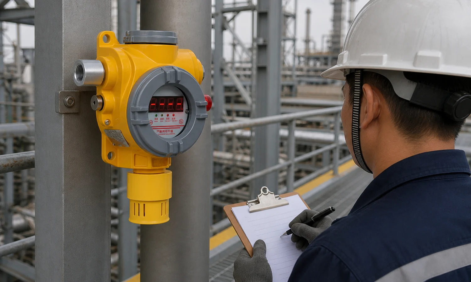
Start with the detector list
- List detector points
- Match input signals
- Map alarm actions
- Test the complete path
Begin at the field, not at the controller catalogue. One room may need several detector points; one point may monitor more than one gas. Neither observation tells you the number of compatible controller inputs until you have listed the actual devices and their configured outputs. A fixed detector’s sensing method also does not, by itself, identify the electrical signal sent to the panel.
For each point, record the tag, area, target gas, measuring range and unit, detector model, selected output, supply requirement and proposed alarm destination. Mark an output as “to confirm” if the detector family offers several versions. A quoted model name without its ordered signal option is not enough for a wiring schedule.
| Point record | Question to answer | Why it matters at the controller |
|---|---|---|
| Gas and displayed unit | Is the point specified in ppm, %LEL or %VOL? | The panel must show and label the reading correctly. |
| Detector output | Which signal and wiring arrangement are ordered? | It determines the compatible input and cable plan. |
| Point count | How many signals are needed now and later? | It sets channel capacity and room for expansion. |
| Response assignment | Which alarm, fault and plant action belongs to this point? | It determines output mapping and the test plan. |

Match inputs before counting channels
Channel capacity matters only after input compatibility is clear. A detector ordered with a three-wire 4–20 mA output needs a suitable analogue input and power arrangement. A detector ordered with an RS485 bus output needs a compatible digital interface and communication settings. The connector count shown on a catalogue page is not proof that both versions can be connected in the same way.
Check the signal type, terminal assignment, supply voltage, communication details where applicable, and the permitted cable arrangement in the exact documents supplied for both devices. For a retrofit, add the existing cable cores and route to the schedule. That small step can reveal a mismatch before a new panel is ordered.
Size the controller for current points and a defined expansion plan
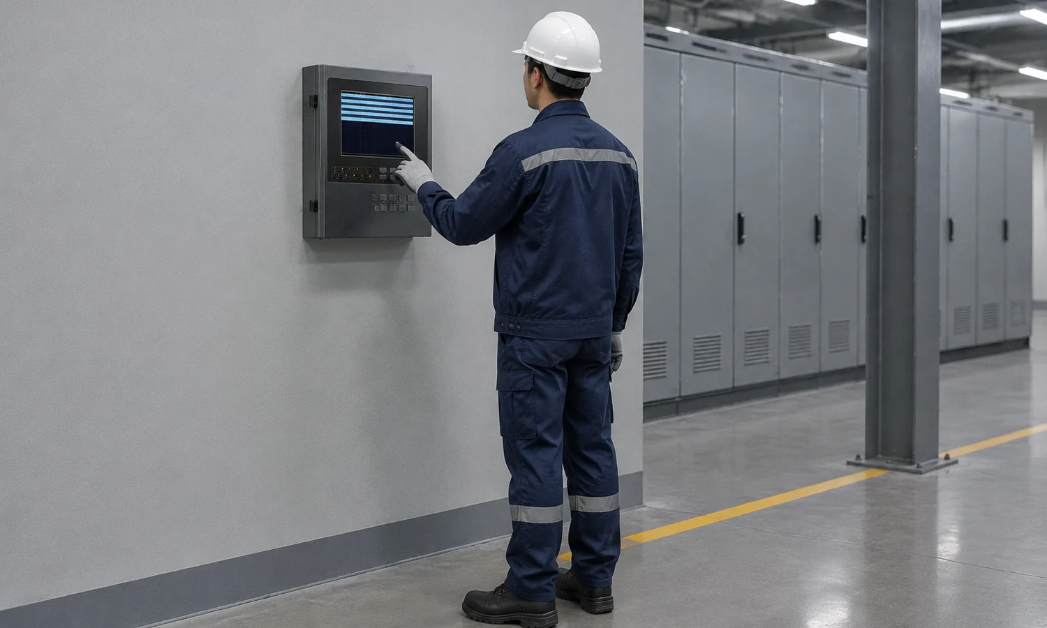
Count the detector signals that the controller must receive today, then list the points already planned for later phases. Do not turn an unspecified hope for expansion into a fixed percentage of spare channels. Write down the additional tags, their likely signal types and when they may be installed. A spare input is useful only if the correct input type, enclosure space, supply and output capacity are available when that point is added.
Also decide whether operators need one central view of several areas or separate local panels. This is an operating and wiring decision, not simply a comparison between “single-channel” and “multi-channel” product labels. The answer affects where alarms are seen, who acknowledges them and which equipment each output can control.
Write the alarm action before choosing the output
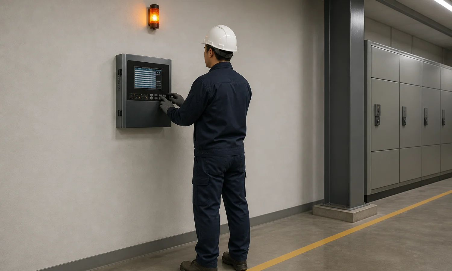
An alarm level is a decision point; an output is how that decision reaches someone or something. Map the required actions separately: an on-panel indication, a local sounder or beacon, a signal to a building or process system, ventilation, or a shutoff command. A fault condition needs its own treatment so a lost detector signal is not mistaken for a safe reading.
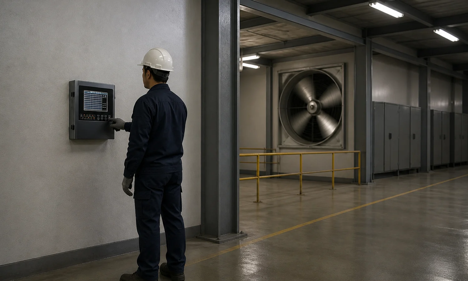
For each action, record the originating detector or group, the trigger condition, the receiving device, reset or acknowledgement behavior, and the output to be tested. If ventilation is part of the response, specify the actual interface to its starter or control system. The controller output rating and the load or interposing relay arrangement must agree with the electrical design.
Otywell products to review for the point schedule
These pages cover the controller and three detector configurations relevant to the questions above. Select the gas, range and output option for each detector before checking the final connection schedule.
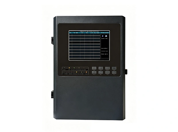 Controller
GDB9 Intelligent Gas Alarm Controller
Listed 4–20 mA and RS485 signal handling, configurable alarms, relay outputs and event views. Confirm the selected channel and power configuration.
View product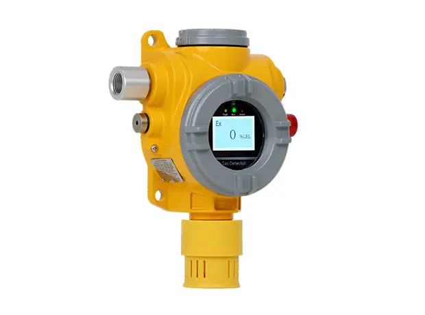 Fixed point
GTYQ-TCB2 Point-Type Gas Detector
Fixed-point diffusion detection with local sound and light indication. Specify the gas, measuring range and ordered output signal.
View product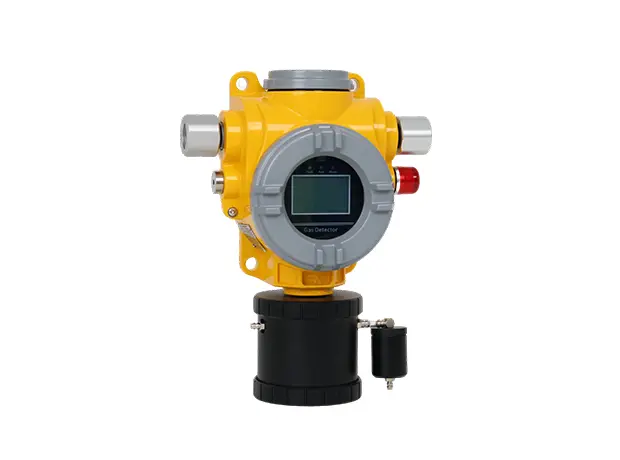 Pump suction
TCB2-B Pump-Suction Point-Type Gas Detector
Integrated pump-suction sampling with local indication and listed plant-signal options. Check the sample line and ordered output.
View product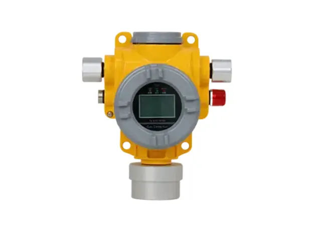 Gas combination
TCB2-F Point Type Four Gas Detector
Optional one-to-four-gas configuration at a fixed point, with local alarms and listed control-system outputs. Confirm the actual gas combination.
View productCheck the installation and operator workflow
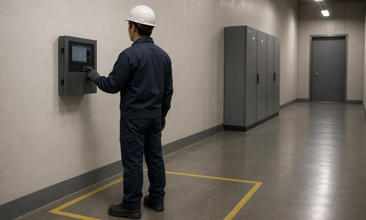
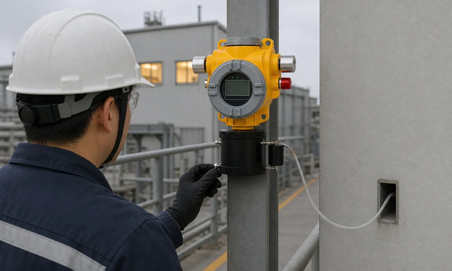
Panel location affects routine use. The display, acknowledgement controls and maintenance access should be practical for the person who will respond to an alarm. Put the controller position, cable entry, power arrangement and expected operator route on the drawing. Where a detector uses a sample line, include the sampling point and line in the commissioning record; an indication at the panel is only the last part of that path.
Review what happens after a mains interruption, a detector disconnection and a restored normal signal. Record whether an alarm must be acknowledged or manually reset. These choices belong in the operating sequence and the acceptance test, rather than being decided when the installer first opens the controller menu.
Test the complete path at commissioning
A controller display that powers up has passed only the first check. The commissioning record should identify each detector tag and confirm the correct displayed gas and unit, alarm level, local indication, remote notification, relay action and fault response. The point that actuates a ventilation fan or another device should be traced through to that device rather than stopping the check at the panel relay.
For a pump-suction point, include the inlet, tubing and detector response in the test arrangement. Keep a record of configuration values and the final as-built point schedule. When a detector is replaced or an input is reassigned later, that record makes it possible to compare the new configuration with the accepted one.
For a point-by-point record covering detector response, channel mapping, alarm actions and handover, use the fixed gas detection system commissioning checklist.
A gas alarm controller selection checklist
Use one row per detector signal. The final column should contain an answer or a document reference before the equipment order is released.
| Check | Record before ordering | Verify at handover |
|---|---|---|
| Detector point | Tag, location, gas, range and unit | Correct tag and reading shown |
| Input | Ordered output, panel input and wiring arrangement | Signal received and fault recognized |
| Capacity | Used channels and named future points | As-built channel schedule retained |
| Alarm action | Level, sounder, beacon, relay and receiving equipment | Each assigned response demonstrated |
| Power and access | Supply, backup arrangement if specified, panel location | Power changeover and access checked |
| Service | Sampling line, calibration access and record location | Maintenance route and configuration documented |
Review the controller options
Once the point schedule is complete, review Otywell’s gas alarm controllers against the required inputs and actions, then specify the configuration with the detector list attached.
Frequently asked questions
How many controller channels do I need?
Start with the number of detector signals to be connected now. Add only future points that are identified in the expansion plan, and check that their input types, power and output needs can also be accommodated.
Can a 4–20 mA detector connect to any gas alarm controller?
No. The controller needs a compatible analogue input and the correct wiring and supply arrangement. Compare the ordered detector version with the exact controller terminal and input specifications.
What is the difference between an alarm output and a fault output?
An alarm output reports a configured gas condition. A fault output reports that part of the detection path cannot operate as intended, such as a monitored signal problem. Give each state its own response in the output schedule.
When should I consider a multi-channel controller?
Consider one when several detector points must be viewed and acted on from a common location. The deciding details are the point count, input types, alarm groups, operator workflow and planned expansion.
What should I check before connecting ventilation or a shutoff valve?
Define the trigger, the receiving equipment, relay or interface requirements, reset behavior and the functional test. The controller’s available output and its rating must match the electrical design for that action.
What should be tested before the system is handed over?
Trace each tagged detector to the displayed reading, alarm and fault indications, assigned outputs and receiving devices. Keep the tested settings and as-built point schedule with the handover record.