
Gas Station Gas Detection System: Gasoline Vapor Monitoring Solution
A gas station gas detection system has to answer more than whether a detector can sense a combustible gas. At a fuel dispenser, the useful questions are where gasoline vapor could reach a sensing inlet, how a warning reaches the right person, and whether the complete path still works after installation. This solution uses Otywell magnetic wireless detectors at selected forecourt points and treats the site layout, target-vapor configuration and alarm route as one design.
Application: gasoline dispensers and nearby equipment enclosures. Primary fixed point: BTYQ-GYQ-TCB2 magnetic wireless combustible-gas detector, ordered for the confirmed gasoline-vapor configuration. Alarm path: local sound and light indication, plus the selected wireless reporting route and a defined receiver. Design gate: verify each sensing position, radio path, hazardous-area suitability and gas-specific calibration before handover.
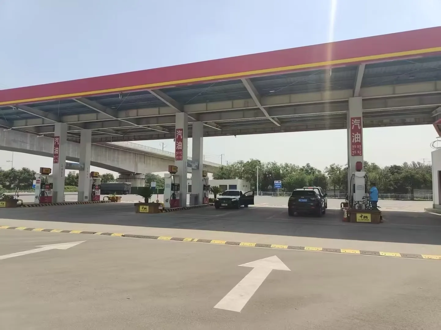
The monitoring task: recognize vapor at the right point
Gasoline vapor can be released during a spill, a hose or connection fault, or work around fuel-handling equipment. The UK Health and Safety Executive’s petrol-dispensing guidance notes that vapor can travel and collect in low or poorly ventilated spaces. A dispenser-mounted instrument measures air at its own inlet. It cannot be assumed to cover an under-dispenser void, tank access chamber or distant cabinet simply because those places are on the same forecourt.
For this solution, the site survey should identify a credible release, the route vapor may take, and the location where a sensor can encounter it. Air movement, enclosure openings, obstructions, routine cleaning and service access can all change the value of a proposed point. Vapor density informs the review, but it does not replace a walk of the actual dispenser and its surroundings.
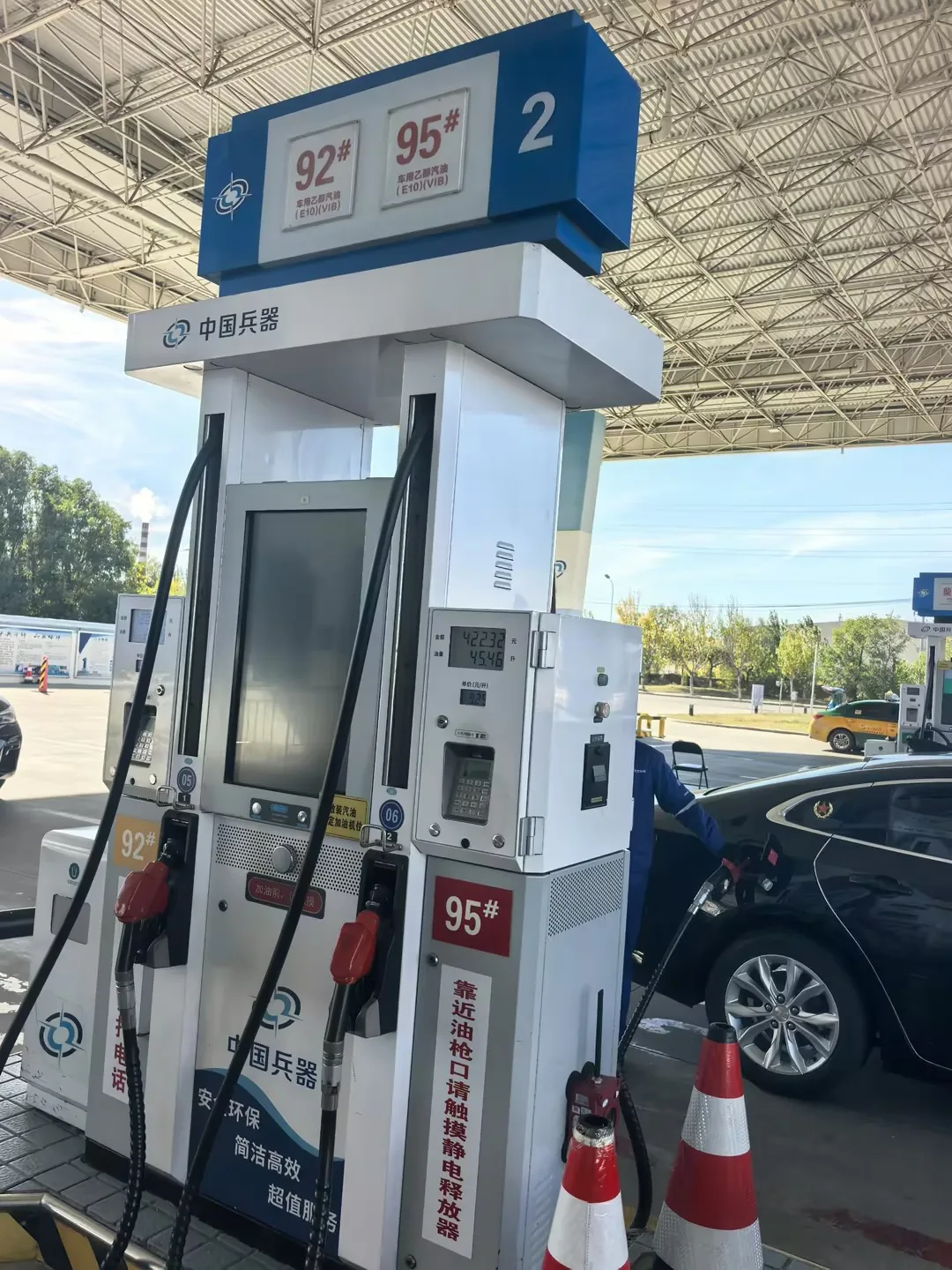
A point layout built around the dispenser
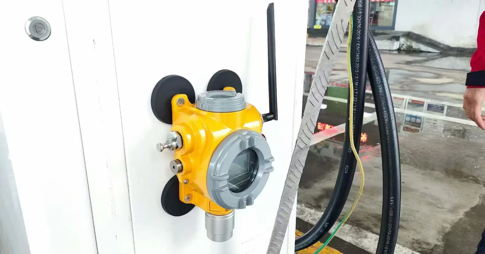
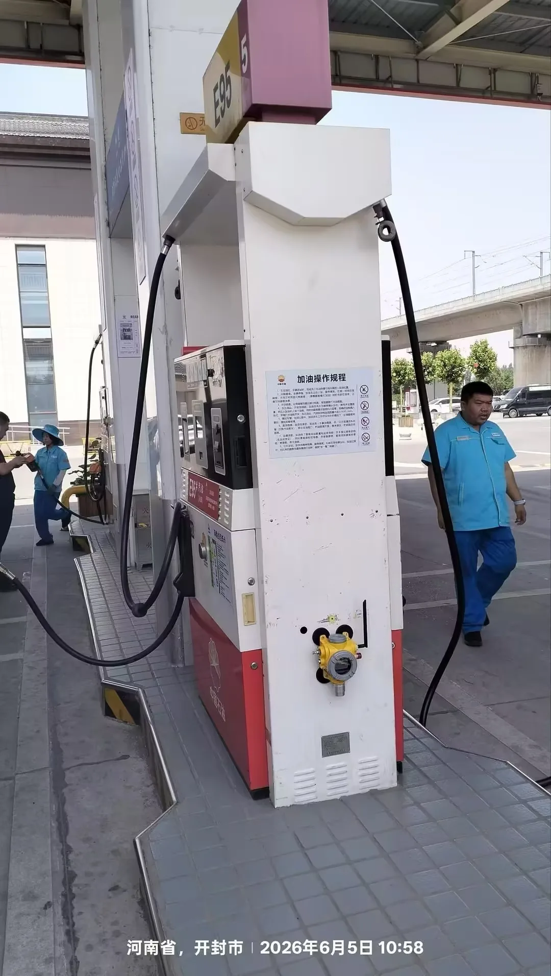
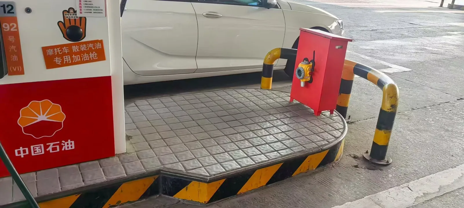
The field images show an Otywell detector beside hoses, another on the lower side of a dispenser, and one on a nearby cabinet. These are examples of mounting arrangements, not a prescribed height or a single station’s complete installation. A suitable metal surface can simplify mounting, but the position must leave the gas inlet open and be accessible for inspection without obstructing dispenser use.
| Area to review | What to check on site | Point decision |
|---|---|---|
| Dispenser hose and connection area | Likely release position, openings, airflow and physical impact | Locate a fixed inlet where vapor from the defined release can reach it. |
| Lower dispenser or cabinet enclosure | Panels, cavities, ventilation and access for testing | Use a separate point or sampling route if the enclosure is isolated from the first inlet. |
| Tank access chamber or other low space | Whether vapor can accumulate and whether the space is connected to the dispenser area | Assess it as its own monitoring location; do not assign coverage from a distant dispenser point. |
| Alarm-receiving location | Wireless coverage, receiver, point identification and the after-hours response | Prove that the correct event arrives where somebody can act on it. |
From a sensing point to a usable alarm
The photographed BTYQ-GYQ-TCB2 is a battery-powered, magnetic-mount fixed detector with local audible and visual indication. Its public product page describes wireless versions that can report concentration, battery and abnormal-status information. The selected version, receiving device and event-routing method must be named in the station design. A radio signal seen in an office does not establish coverage at every dispenser position.
- Gasoline-vapor point
- Detector and local warning
- Selected wireless link
- Receiver and assigned response
Otywell has confirmed that the units shown in these photos can measure gasoline vapor. The public standard BTYQ-GYQ-TCB2 page lists methane, propane and isobutane, so a gasoline-vapor order needs its own written target-gas, sensor and calibration basis, measurement range and alarm settings. The HSE guidance on flammable-gas detector selection likewise connects sensor selection, placement, alarm response and maintenance.
Where a central controller is required, specify the real interface between the wireless field system and the panel. A controller with 4–20 mA or RS485 inputs is an option for compatible wired detector channels; those inputs alone do not make it a direct receiver for a wireless detector. Define the gateway or alternative receiving path before including a panel in the bill of materials.
Otywell products and their roles in the solution
The photographed wireless detector is the primary fixed point for the confirmed configuration. The other three products are options for a different signal architecture, a sampled location or a portable inspection task; they should be selected only where that role exists in the site plan.
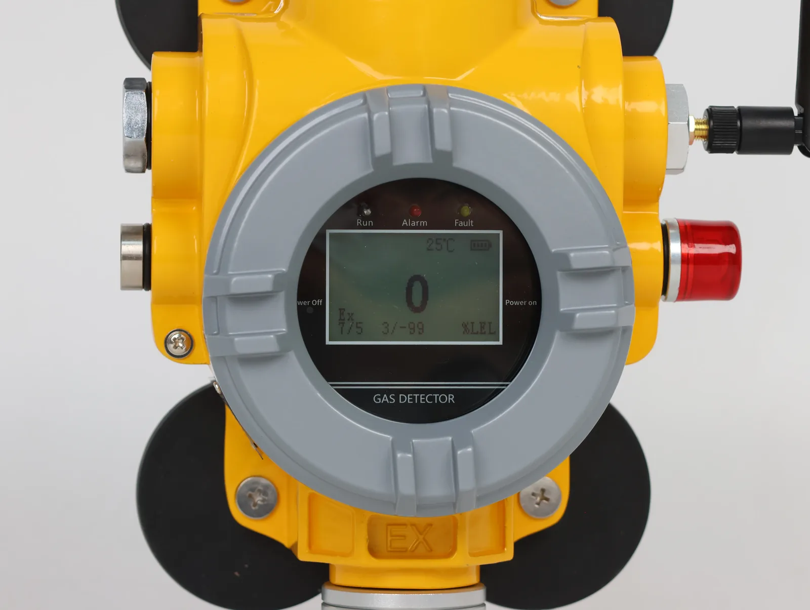 Primary fixed point
BTYQ-GYQ-TCB2 Magnetic Wireless Detector
Magnetic mounting, battery power, local sound and light warnings, and selected wireless reporting. Confirm the gasoline-vapor configuration in writing.
View detector specifications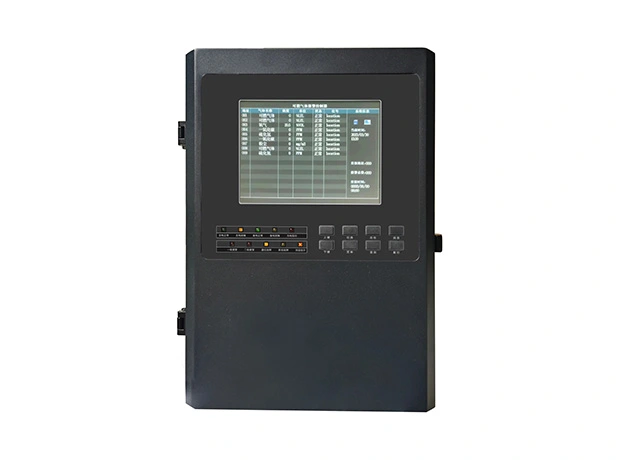 Wired alarm option
GDB10 Intelligent Gas Alarm Controller
Processes compatible 4–20 mA or RS485 channels. A wireless system needs a specified interface before this panel can be included in its alarm path.
Review controller inputs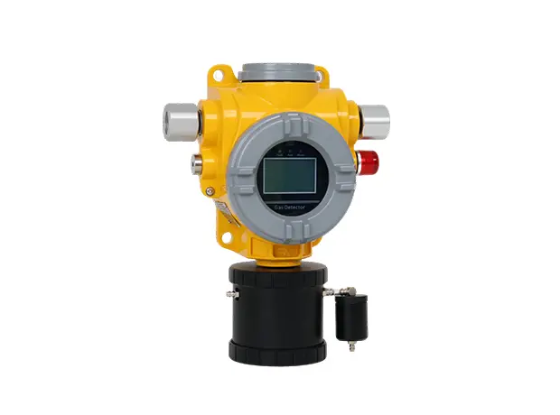 Sampled-point alternative
TCB2-B Pump-Suction Point-Type Detector
Draws a sample to a fixed detector when a direct-inlet position is unsuitable. Define the target vapor, sample route and maintenance access.
Review sampling options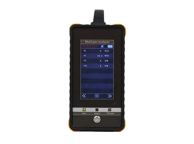 Portable inspection
OT800 Portable Multi Gas Analyzer
Pumped portable sampling for an ordered gas selection. It supports investigation and checks beyond the continuously monitored fixed points.
Review portable analyzerInstallation and commissioning sequence
1. Confirm the gas and the ordered version
Write down gasoline vapor as the target for the pictured configuration, then confirm the sensor, calibration reference, measuring range and proposed alarms for the unit actually supplied. A generic “combustible gas” label is insufficient for acceptance testing. LPG or CNG dispensers, if present, introduce different target gases and require their own selection review.
2. Walk and mark every proposed point
Assign a tag to each dispenser or enclosure location. Photograph the intended surface, check that the inlet will remain exposed, and note likely spill or release paths, cabinet openings, airflow and impact risk. Check the site’s hazardous-area classification against the certificate and marking of the exact ordered version. An enclosure’s water-and-dust rating answers a different question from its hazardous-area approval.
3. Test the communication path in place
Choose the applicable LoRa, NB-IoT or cellular version and test reception from the final mounting position, not just from a temporary location. Record the receiver, point identity, battery-status handling and communication-fault response. If the project uses a separate gateway or controller, show it on a simple signal diagram.
4. Prove the end-to-end response
Use the prescribed test procedure and appropriate gas for the ordered sensor. Observe the reading and local warning, then verify that the correct tagged point appears at the receiver and that the assigned site action follows. Record both gas-alarm and fault behavior. The Otywell controller selection guide is a useful companion when the design includes compatible wired channels and panel outputs.
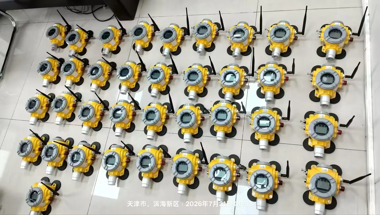
Keep a handover record of detector tag, final position, gas configuration, test result, alarm settings, receiving route and maintenance access. The photographs below show units prepared for installation; they do not establish how many points were finally installed or commissioned at one site.
What to send for a station-specific proposal
A useful brief contains the fuels handled, a marked forecourt layout, photos of proposed detector positions, the target vapor and calibration requirement, the number and identity of monitoring points, any classified-area requirements, available wireless coverage and who should receive each alarm. State whether the project needs local warning only, remote notification, panel outputs or a combination. Otywell can then confirm the suitable detector configuration and the complete reporting path instead of quoting by dispenser count alone.
Review your dispenser monitoring layout with Otywell
Send the point schedule and site photos with your target-vapor and alarm requirements. Ask for a written configuration that ties each sensing point to its receiver, test method and handover record.
Frequently asked questions
Can the photographed wireless detector measure gasoline vapor?
Otywell has confirmed that capability for the photographed units. Request the written target-gas, sensor and calibration details for the version supplied to your project because the public standard specification lists other combustible gases.
Where should a gas detector be placed on a fuel dispenser?
Start with the defined release and the route vapor could take. Choose an accessible surface where the inlet is exposed, then review airflow, cabinet openings, impact risk and the site’s area classification. The photographs illustrate possible positions, not a universal mounting height.
Will one dispenser detector also cover a tank chamber?
No coverage should be assumed from proximity alone. A fixed detector measures the atmosphere at its inlet. An isolated chamber may need its own point or a suitable sampling arrangement after its enclosure and airflow have been assessed.
Does the wireless detector connect directly to the GDB10 controller?
A direct connection is not established by the published specifications. GDB10 accepts compatible wired channels; a wireless design must name its actual receiver and any required gateway or interface before a panel is specified.
What must be checked before the system is handed over?
Verify the ordered gasoline-vapor configuration, each tagged location, hazardous-area suitability, the local gas-alarm response, the correct remote point identity, radio coverage and communication-fault behavior. Record results under the prescribed test procedure.
Does fixed monitoring remove the need for portable checks?
Fixed units continuously watch selected points. A portable instrument configured for the target gas can support investigations or checks at other locations. Its gas selection, range and sampling method should be specified for that separate task.